Solar chimney
 The measurement of test solar chimneys began in March 2003. It is obvious from the
design of the experimental device the results of winter measurement or more specifically under conditions of outdoor
temperature much lower than that of the laboratory hall indoor are not much of an interest. Under such conditions, the
main driving force that causes ventilation is buoyancy due to the temperature difference between the hall interior and
exterior, hence the solar chimney acts as a traditional stack ventilation shaft. Neither are the mentioned conditions
interesting from the point of view of a solar chimney, because the traditional stack ventilation is usually capable of
meeting the required air change. In addition, natural ventilation makes it rather difficult to employ any heat recovery
equipment which might constrain its utilisation, and thus solar chimney application, to situations in which ventilation
does not represent an unacceptable heat loss.
The measurement of test solar chimneys began in March 2003. It is obvious from the
design of the experimental device the results of winter measurement or more specifically under conditions of outdoor
temperature much lower than that of the laboratory hall indoor are not much of an interest. Under such conditions, the
main driving force that causes ventilation is buoyancy due to the temperature difference between the hall interior and
exterior, hence the solar chimney acts as a traditional stack ventilation shaft. Neither are the mentioned conditions
interesting from the point of view of a solar chimney, because the traditional stack ventilation is usually capable of
meeting the required air change. In addition, natural ventilation makes it rather difficult to employ any heat recovery
equipment which might constrain its utilisation, and thus solar chimney application, to situations in which ventilation
does not represent an unacceptable heat loss.
The measurement of test solar chimneys began in March 2003. It is obvious from the design of the experimental device the results of winter measurement or more specifically under conditions of outdoor temperature much lower than that of the laboratory hall indoor are not much of an interest. Under such conditions, the main driving force that causes ventilation is buoyancy due to the temperature difference between the hall interior and exterior, hence the solar chimney acts as a traditional stack ventilation shaft. Neither are the mentioned conditions interesting from the point of view of a solar chimney, because the traditional stack ventilation is usually capable of meeting the required air change. In addition, natural ventilation makes it rather difficult to employ any heat recovery equipment which might constrain its utilisation, and thus solar chimney application, to situations in which ventilation does not represent an unacceptable heat loss.
The data acquisition software was developed in the Laboratory of cumputer-aided measurement. It employs an ADAM 5000/TCP unit which resides in one of the the hall switchboards underneath the chimney. The measured data are fed into the software, running on a server, using a TCP network environment. The software stores the measured data into an SQL database (Firebird 2.0) and generates a chart visualization of the data; it also provides an option to export it in MS Excel format for further processing.
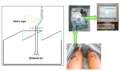
Measuring frequency is 10 seconds, but the data stored and visualized at the 3 minute interval are that of a running average.
Table of measured parameters
| Solar radiation [W/m2] measured with Kipp Zonen pyranometer | Pressure difference between building interior and exterior [Pa] |
| Wind speed [m/s] |
Wind direction [] |
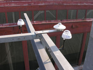
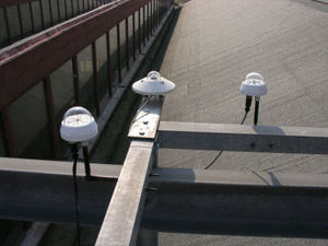
| Air speed in thermal mass chimney duct [m/s] side # 1 | Air speed in thermal mass chimney duct [m/s] side # 2 |
| Air speed in light weight chimney duct [m/s] side # 1 | Air speed in light weight chimney duct [m/s] side # 2 |
| Hall temperature prior to chimney entry [°C] | Outdoor temperature [°C] |
| Light weight chimney temperature above glazing [°C] | Thermal mass chimney temperature above glazing [°C] |
| Light weight chimney exit temperature [°C] | Thermal mass chimney exit temperature [°C] |
| Metal plate temperature (light weight chimney) [°C] | Concrete slab temperature (thermal mass chimney) [°C] |
| Air temperature in duct at ceiling level [°C] | Duct temperature [°C] |
| Hall temperature [°C] | |
| Solar radiation within chimney plane [W/m2] | |