
Building up an experimental house
The idea to build an experimental house with the aim to do research on ventilation emerged when the Department of Thermodynamics and Environmental Engineering of Faculty of Mechanical Engineering of Brno University of Technology joined RESHYVENT (RESidential HYbrid VENTilation) project under the 5 th EU framework programme. The experimental house was intended for investigation of hybrid ventilation under the Czech Republic conditions at first. The idea of a simple structure which would resemble a laboratory rather than a residential house was soon abandoned though. A new plan was drawn up – a demonstration family house – thermal insulation parameters of which exceeded considerably those required by current standards and which was equipped with a modern hybrid ventilation system along with other energy saving systems related to heating and ventilation. The main idea behind the new plan was to serve the general public and/or the experts as a demonstration project of demand controlled ventilation implementation in the Czech Republic.
Nainstalujte si aktuální verzi přehrávače Flash prosím.

Project background
The idea to build an experimental house with the aim to do research on ventilation emerged when the Department of Thermodynamics and Environmental Engineering of Faculty of Mechanical Engineering of Brno University of Technology joined RESHYVENT (RESidential HYbrid VENTilation) project under the 5th EU framework programme. The experimental house was intended for investigation of hybrid ventilation under the Czech Republic conditions at first. The idea of a simple structure which would resemble a laboratory rather than a residential house was soon abandoned though. A new plan was drawn up – a demonstration family house – thermal insulation parameters of which exceeded considerably those required by current standards and which was equipped with a modern hybrid ventilation system along with other energy saving systems related to heating and ventilation. The main idea behind the new plan was to serve the general public and/or the experts as a demonstration project of demand controlled ventilation implementation in the Czech Republic.
The ventilation system is based on a hybrid ventilation system designed and developed for moderate climate under RESHYVENT project by a consortium of Dutch companies in cooperation with the applied research institute TNO. A heat pump (ventilation air heat recovery) and solar chimney (summer season passive cooling) are the two supplementary components to the system that adjust it to the Czech Republic conditions. Given the limited time for house construction, a wooden structure of high thermal insulation was chosen.
The experimental house for research on ventilation is going to serve both educational and/or demonstration as well as investigation purposes of demand controlled ventilation under the Czech Republic conditions. It is fitted with an extensive measuring system which monitors numerous parameters necessary for assessment of demand controlled ventilation benefits from both indoor air quality and energy saving points of view.
Those interested in the ventilation system along with other HVAC technologies installed or getting installed, and results of ongoing measurements and experiments, will be introduced to it in the presentation room (living room) ground floor situated.
Technical specifications
The experimental house concept is of a detached two-storey family house of a flat roof. From a structure point of view it is a timber frame structure and OSB cladding. Its foundations comprise individual and wall footings. In between the house floor and the ground, there is a ventilated airspace. The flat roof drainage pipe runs centrally through the house.
The ground and net floor areas of the house are 72.4 m2 and 101 m2, respectively. Top views of both floors are depicted in Fig. 3. Since the house is intended for demonstration, it is wheelchair accessible to its ground floor, where there is the presentation room there, via a barrier free pavement.
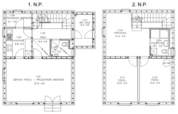
Fig. 3 – Top views of ground and first floors of the experimental house
Thermal insulation of perimeter walls and other constructions
The house is very well thermally insulated; the overall thickness of thermal insulation is 300 mm for all perimeter walls. Walls and roof and floor constructions are filled with mineral wool in the space among the supporting beams and joists. 80 mm thermal insulation system is applied to the exterior side of perimeter walls, whereas the interior side insulation thickness is 60 mm and fills up the space between the supporting frame of plasterboard cladding.
Fig. 4 depicts a perimeter wall along with its composition. The thermal transmittance of the wall, U, is 0.15 W·m-2·K-1. Despite the low value of the thermal transmittance, the overall thickness of the wall is 320 mm, as can be seen in the figure, which is quite small a value.
The flat root composition is illustrated in Fig. 5. The thermal transmittance of the roof, U, is 0.15 W·m-2·K-1 excluding the thermal resistance of polystyrene panels that make up the inclined roof surface in order to direct rain water towards the drainage pipe. It also excludes the thermal resistance of gravel which protects the waterproofing layer.
Fig. 4 – Composition of wall construction
Fig. 5 – Composition of roof construction
The floor composition at the ground floor is depicted in Fig. 6. Its thermal transmittance is the lowest of all perimeter constructions, namely U = 0.14 W·m-2·K-1. The living room and sanitary facility of the ground floor are fitted with floor heating. Apart from 300 mm of mineral wool, the floor consists of Styrodur® panels which embed the floor heating system and level the floor of other rooms with that of the living room.
Fig. 6 – Composition of floor construction
The thermal transmittance of windows and external doors is 1.1 W·m-2·K-1. It can be generally said the thermal transmittance of all perimeter constructions considerably exceeds the standard requirements.
Heating
The experimental house employs a warm water heating system in combination with a heat storage tank of 400 l to overcome its winter heat loss. It is a low temperature system in which radiators operate between 50 and 40 °C of water temperature and the floor heating between 35 and 30 °C. It aims at the best utilisation of solar panels gathered energy as well as heat pump for heat recovery from the exhaust air. The domestic hot water is provided via flow-through heater located in the heat storage tank; see Fig. 7 for the system schematics.
There are two evacuated tube collectors of 6 m2 total area. They are of VS 40-S enlarged type by Vacusol. Although the evacuated tube collectors are more expensive than the flat ones, their performance is better (greater efficiency) at low exterior temperatures. Therefore they may cover substantial portion of energy required for heating since the house heat loss is very low.
According to the producer, the employed evacuated tube collectors may gather between 650 and 850 kWh/m2 of solar heat energy annually under the Czech republic climate, which represents 3900 and 5100 kWh, respectively, for the 6 m2 of collectors installed.
The heating system of the presentation room (living room) combines both radiators and underfloor heating to meet its demonstration as well as experimental purpose. Either subsystem is sized to cover completely the room heat loss, the aim being to investigate and, later on, demonstrate the performance of the hybrid ventilation system with either radiator or underfloor heating or their combination and the effect on thermal comfort.
Fig. 7 – Schematics of the experimental house heating system
| 1 Temperature stratified heat storage tank of 400 litres in volume with a flow-through heater, solar system
heat exchanger and electric cartridge heater of 6 kW in power 2 Evacuated tube collectors (2× 3 m2) 3 Air-water heat pump for heat recovery from exhaust air |
Ventilation
Fig. 8 – Placement of a self-regulating outlet |
The house is equipped with a hybrid ventilation system. It combines natural and mechanical ventilation to minimise energy consumption. It is based on a hybrid ventilation system developed by a consortium of Dutch companies in the frame of RESHYVENT project. Hybrid ventilation systems can be divided into tree principal categories. The one applied in the house falls into the category called 'fan assisted natural ventilation'. If possible, the system employs natural forces for it operation (temperature difference, wind); when these are insufficient for ensuring the required ventilation rate, the fan is put into operation.
The system consists of self-regulating outlets for air supply, air ducts, exhaust air fan, ventilation roof cowl (wind utilisation), central control unit and CO2 sensors.
The self-regulating outlets are located above windows or doors of the house living space (Fig. 8). They make use of servo actuators to keep the air flow rate fixed at the user or system set level regardless of the pressure difference at the building façade. The system is designed to achieve the nominal air flow rate at the pressure difference as low as 1 Pa. Fig. 9 illustrates the outlet principle of operation.
|
Fig. 9 - Principle of self-regulating outlet operation |
Exhaust air is extracted from the house via exhaust outlets located in the kitchen, bath room and sanitary facility.
Monitoring of CO2 concentration provides data for automatic control of ventilation in living spaces (Fig. 10). There are four CO2 sensors in the house placed in the living room, study and both bedrooms. When the concentration of CO2 exceeds the pre-set limit, the supply air outlet opens providing the fresh air to the room environment until the concentration crosses the lower pre-set limit. Both CO2 concentration limits can be set in the central control unit – e.g. 800 ppm for opening and 600 ppm for closing the outlets.
By using the demand controlled ventilation, the overall ventilation air change rate can be reduced while maintaining the indoor air quality, which significantly decreases the ventilation heat loss.
In order for the demand controlled ventilation to operate efficiently, the house must be quite airtight. For the particular system it is required that N50 < 3, meaning the air change rate at 50 Pa of pressure difference must be smaller than 3. In case of low airtightness, the external air infiltration reaches considerably high level and hereby deteriorates the efficiency of the controlled ventilation. Furthermore, the heat loss associated with the high infiltration rate diminishes the benefit arising from low thermal transmission loss. Therefore, great attention was paid to the experimental house airtightness. Experiments conducted in February 2003 showed, the achieved airtightness was N50 = 2.5 1/hour.
Fig. 10 – Schematics of the hybrid ventilation system
A remote control similar to that used for TV or other electronics control is available for user interaction with the supply air outlets. The user is thus free to adjust the system operation any time; to close the supply outlet when feeling an inconvenient level of draught for instance. After such user action, the system will stay in the user set mode for a predefined time period, e.g. 6 hours, and then it will resume to its pre-set automatic operation (see Fig. 13).
In order to reduce the ventilation heat loss, an air-to-water heat pump with a 270 litre heat storage tank is installed in the house to recover heat from exhaust air. Warm water can be pumped between the system heat storage tank and that of the heat pump automatically, based on the temperature difference. The heat pump operates when the air flow rate exceeds 35 l/s.
There is also a solar chimney installed above the stairwell of the house. It intensifies the ventilation during the warm season when the air change does not cause ventilation heat loss but the contrary, i.e. helps remove ventilation heat load. The solar chimney is an experimental device which benefits of to the thermal comfort and indoor air quality will be studied in oncoming years. In principle, the solar chimney is an air-heating collector that employs sun to heat up passing air and to amplify the driving force of natural (stack) ventilation.
Testing of the demonstration house ventilation system function
Because the demonstration house is not yet permanently occupied, the CO2 concentration indoors mimics that of outdoors. Fig. 11 shows the concentration in individual rooms along 5 day time period.
Fig. 11 - CO2 concentration indoors (unoccupied)
As can be seen, the CO2 concentration was around 400 ppm, hence below the opening limit of the supply outlets.
Therefore it was necessary to simulate presence of people in order to verify the system performance. This was achieved by releasing CO2 within the room. The occupancy was simulated in the living room by releasing a constant flow rate of 36 litres/hour of CO2. The experiment arrangement is depicted in Fig. 12. At this occasion, the accuracy of the CO2 sensor was also assessed, employing Bruel and Kjaer 1302 gas analyser. The sampling tube for the gas analyser was located close to the CO2 sensor while the gas analyser itself resided in the kitchen separated by a chipboard replacement of the respective door.
Fig. 12 – Simulation of occupancy
The chart in Fig. 13 shows CO2 concentration and air flow rate across the outlet throughout 4 days of simulated occupancy. During the inspected time period, a user invoked closing of the outlet was simulated which resulted in a raised CO2 concentration level in the room. The experiment conducted proved the ventilation system be functional. It was capable of maintaining the CO2 concentration below 1200 ppm when set up to the programmed ventilation regime (see right hand side of the chart).
Fig. 13 – CO2 concentration and flow rate across the outlet in the living room